BACKGROUND
The Rev 1.0 UDM counterweight system was designed to work with a tool head weight between 75 and 100 grams. Any weight outside these parameters will cause the machine to give off excess vibration. As customers are telling use they want to use larger backing plates and the Edge2000 quick-release system with their UDM, we have undertaken a project to design a new system that will work with a wide range of adapters.
The UDM Rev 1.0 counterweight/bearing shaft system was not designed by The Perfect Shine, LLC. The device was designed and produced by a tool manufacturer in China to overcome the patent protection held by Porter Cable in US Patent 5,061,090. The Porter Cable design is significant in the way it retains the bearing assembly without using circular clips as a retaining mechanism. Instead, a rubber key is used, which also serves to keep the bearing from spinning inside the cylinder. The Porter Cable invention is elegant in its simplicty.
OFF SHORE DESIGN
The off-shore solution to overcome the Porter Cable patent is to use a two-part assembly. The bottom half provides the cylinder for the offset bearing shaft (eccentric) and the top half acts as a top hat to retain the bearing shaft assembly and provides the counterweight necessary to balance the rotating mass.
NEW DESIGN
Our goal in developing a new design was to find the flaws in the two previous designs, engineer them out, and develop new retaining mechanisms that will not violate previous invention.
We reverse engineered each design by creating an exact model, including their material density, in SolidWorks. I have attached a view of the Porter Cable system so you can see what the basic reverse engineering model looks like.
In both of the previous models we discovered rotating mass flaws that prevent the tools from operating with less vibration. We also discovered that both designs really thrash the bearings which will cause long-term reliability issues.
I also did not like the two part design of the current UDM assembly or the massive slap-on counterweight design that Porter Cable uses. I really wanted a unitized rotor design with the use of small, incremental weight for fine balancing.
Our challenge became working with three parameters that we derived from the baseline (PC) design. These are: The mass of everything - let's call it the "composite mass"; the position of the center of gravity along the axis of rotation - call this "X", and the distance of the CG away from the axis - call this "Y". If we accomplish this, then the assembly should run smoothly right from the get-go. With three interactive parameters, the process of matching the parameters by changing the CAD model could be VERY messy. Changing one parameter changes the other two.
Our first design idea was to put a couple of good size holes in the counterweight mass. This had the effect of "de-coupling" the Y position adjustment from the other two to a degree, since by moving the position of the holes doesn't change the weight nor does it change the X - it only changes Y. Tricky! After another design review we discovered we could do a better job by adding a small amount of mass 90 degrees out of phase of the CG. It pays to think outside of the box!
Our design has now passed the inspection of the tool maker and our legal folks (who want to patent everything!), so later this week we will start the rapid prototype process.
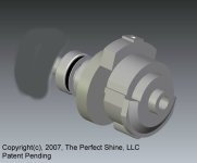
I attached an image of our design. I blanked out our retaining mechanism and can't show you a top view just yet. When the prototype inventions prove to balance out and retain the bearings up to 12,000 RPM, then I will show a picture.
The Rev 1.0 UDM counterweight system was designed to work with a tool head weight between 75 and 100 grams. Any weight outside these parameters will cause the machine to give off excess vibration. As customers are telling use they want to use larger backing plates and the Edge2000 quick-release system with their UDM, we have undertaken a project to design a new system that will work with a wide range of adapters.
The UDM Rev 1.0 counterweight/bearing shaft system was not designed by The Perfect Shine, LLC. The device was designed and produced by a tool manufacturer in China to overcome the patent protection held by Porter Cable in US Patent 5,061,090. The Porter Cable design is significant in the way it retains the bearing assembly without using circular clips as a retaining mechanism. Instead, a rubber key is used, which also serves to keep the bearing from spinning inside the cylinder. The Porter Cable invention is elegant in its simplicty.
OFF SHORE DESIGN
The off-shore solution to overcome the Porter Cable patent is to use a two-part assembly. The bottom half provides the cylinder for the offset bearing shaft (eccentric) and the top half acts as a top hat to retain the bearing shaft assembly and provides the counterweight necessary to balance the rotating mass.
NEW DESIGN
Our goal in developing a new design was to find the flaws in the two previous designs, engineer them out, and develop new retaining mechanisms that will not violate previous invention.
We reverse engineered each design by creating an exact model, including their material density, in SolidWorks. I have attached a view of the Porter Cable system so you can see what the basic reverse engineering model looks like.
In both of the previous models we discovered rotating mass flaws that prevent the tools from operating with less vibration. We also discovered that both designs really thrash the bearings which will cause long-term reliability issues.
I also did not like the two part design of the current UDM assembly or the massive slap-on counterweight design that Porter Cable uses. I really wanted a unitized rotor design with the use of small, incremental weight for fine balancing.
Our challenge became working with three parameters that we derived from the baseline (PC) design. These are: The mass of everything - let's call it the "composite mass"; the position of the center of gravity along the axis of rotation - call this "X", and the distance of the CG away from the axis - call this "Y". If we accomplish this, then the assembly should run smoothly right from the get-go. With three interactive parameters, the process of matching the parameters by changing the CAD model could be VERY messy. Changing one parameter changes the other two.
Our first design idea was to put a couple of good size holes in the counterweight mass. This had the effect of "de-coupling" the Y position adjustment from the other two to a degree, since by moving the position of the holes doesn't change the weight nor does it change the X - it only changes Y. Tricky! After another design review we discovered we could do a better job by adding a small amount of mass 90 degrees out of phase of the CG. It pays to think outside of the box!
Our design has now passed the inspection of the tool maker and our legal folks (who want to patent everything!), so later this week we will start the rapid prototype process.
I attached an image of our design. I blanked out our retaining mechanism and can't show you a top view just yet. When the prototype inventions prove to balance out and retain the bearings up to 12,000 RPM, then I will show a picture.
")